In collaboration with Amazon’s Robotics Team, this project aims to develop a floor-marking robot to scout and place identifying markers around an Amazon warehouse.


Introduction
This project follows a senior design capstone led by myself, Shiv Khanna, Marc Alenn Jean Mary, and Tristan Martello, under the guidance of Amazon Robotics. Once a new Amazon warehouse is built, thousands of markings must be placed on the floor to indicate the locations and orientations of various systems. Amazon’s current method for placing these markings is slow, expensive, and inefficient, so our goal for this project was to create a robot that can complete this process autonomously, quickly, and consistently.
User Needs & Engineering Requirements
The design process for the autonomous floor marking system needed to prioritize key user needs to address the challenges outlined in the problem statement effectively. Our project had two primary user teams, each with a separate set of needs: the Amazon Robotics team and the fiducial-placing team. The Amazon Robotics team oversees how robots work within the warehouses and manages safety, integration, and feasibility. The fiducial-placing team is currently the group of employees responsible for placing robot fiducials after the floor has been marked by the survey team. The teams' needs, as well as how we interpreted them into engineering requirements, are explored in the tables below.
Concept Generation
Since there were no strict limitations as given by Amazon’s team, we attempted to come up with as many viable material ideas as possible. Our six contenders ended up being spray paint, markers, laser engraving, dust/chalk, stickers, and stamps. We then began a large list of pros and cons, which might have been that the material was cheap and easy to restock, but incredibly difficult conceptually to apply to a concrete surface. The general factors we wanted to keep in mind were: ease of application, ease of refill, price, damage to floor/removability, complexity of surrounding controller mechanism, marking design flexibility, clarity of marking, and safety.
Sketches by Tristan Martello
Sketches by Tristan Martello
Finalized Steps
Finally, we concluded that stamps would be our best option. We would "print" four hexadecimal digits since it would supply ~65,000 individual codes, surpassing our initial goal of over 10,000. Drafts were made of conveyor designs to rotate the stamps upside-down and then be moved vertically, but we decided to create a “stamper wheel” that would feature 16 stamps placed on the outer edge of a thin disk. The entire wheel would raise and lower for character placement.
We took a lot of inspiration from 3D printers. Primarily, their use of stepper motors and lead screws for precise vertical and horizontal movement. This meant we would have three degrees of motion: vertical movement of a "chassis", horizontal movement of the wheel via a "slider", and the turning of the wheel itself to new letter stamps. Together, this should allow enough freedom to efficiently print the four characters we needed.
Prototype A
I modeled and helped create the chassis with two custom 3D-printed parts, which held the opposing motors in place and allowed for the attachment to the vertical lead screws. Basic attachments were made for the vertical lead screw motors, and I cut 30mm aluminum to length with a miter saw and helped to fasten them together to make a frame.
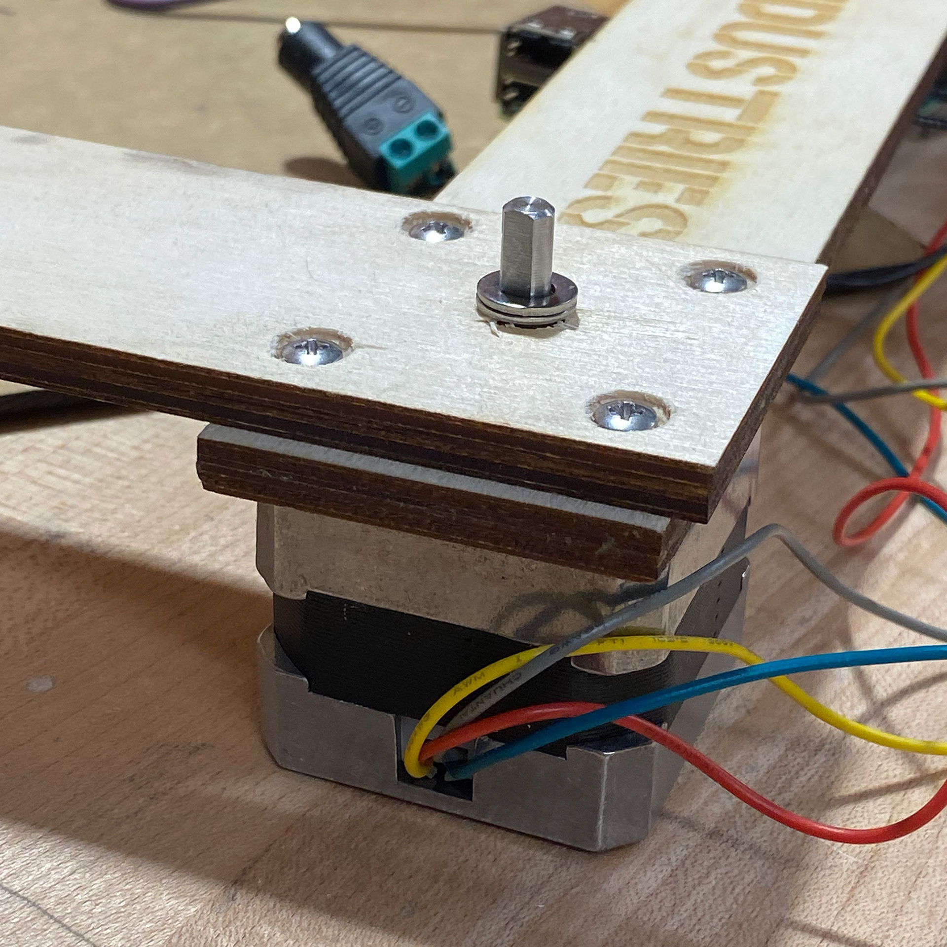
I created a keyed shaft for the motor from an aluminum rod using a mill, lathe, drill press, and screw tapper. This allowed for the stamper wheel to slide horizontally, but still be turnable from the rod itself.
I wrote a custom stepper motor library and stamper protocol in Python to control the main actions and testing, which was run on a Raspberry Pi 4 that was wired to each of the four stepper motors. While wall power was used during much of the testing, an 11.1V lipo battery was used to power the motor drivers, and a 5V portable battery powered the Pi.
An image of me working on assembling the wheels onto the chassis.
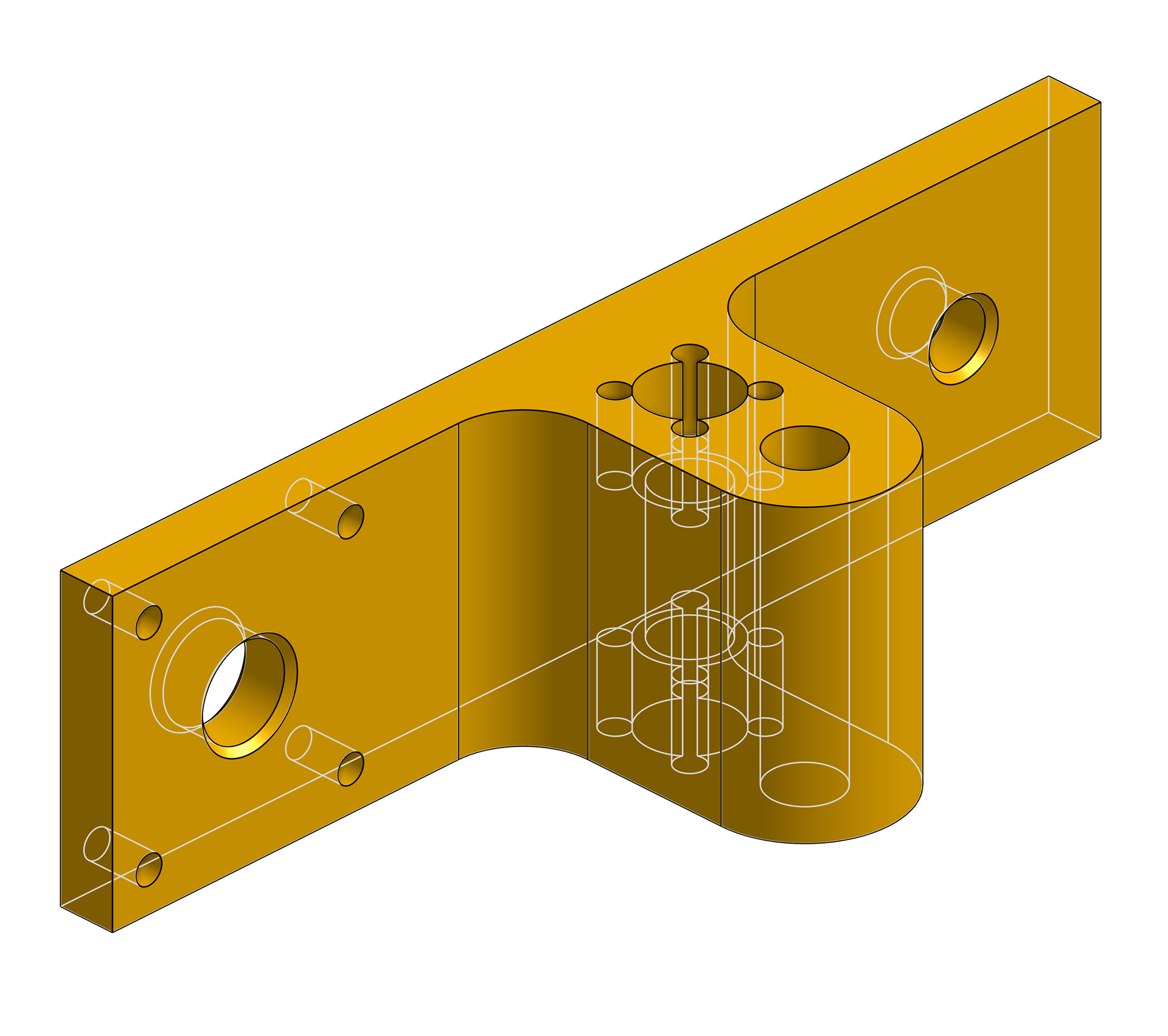
A model of Holder A in the Chassis.
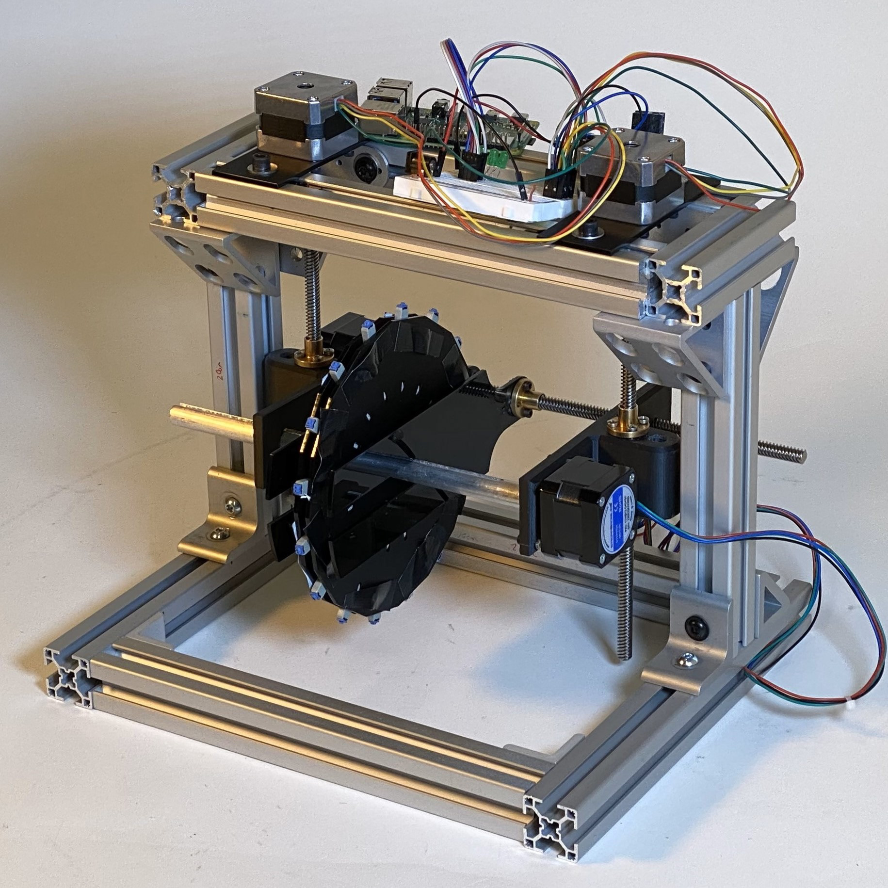
The completed Prototype A.
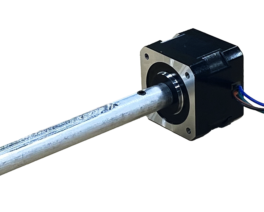
The fabricated keyed shaft on a stepper motor.
Troubleshooting & Designing Prototype B
The first prototype was very helpful in pointing out the problem points with our design. These mainly came down to frame size, stamper wheel size, slider catching, and chassis instability. The stamper wheel size was an easy fix since flatter, larger stamps led to more legible markings, a smaller wheel, as well as a smaller chassis overall. We again, took more inspiration from existing 3D printers to add two additional support rods, that helped to stabilize the now-smaller chassis as it moved vertically. Our second design included a custom-milled keyed shaft since our first iteration had many imperfections that led to increased stamper wheel binding.
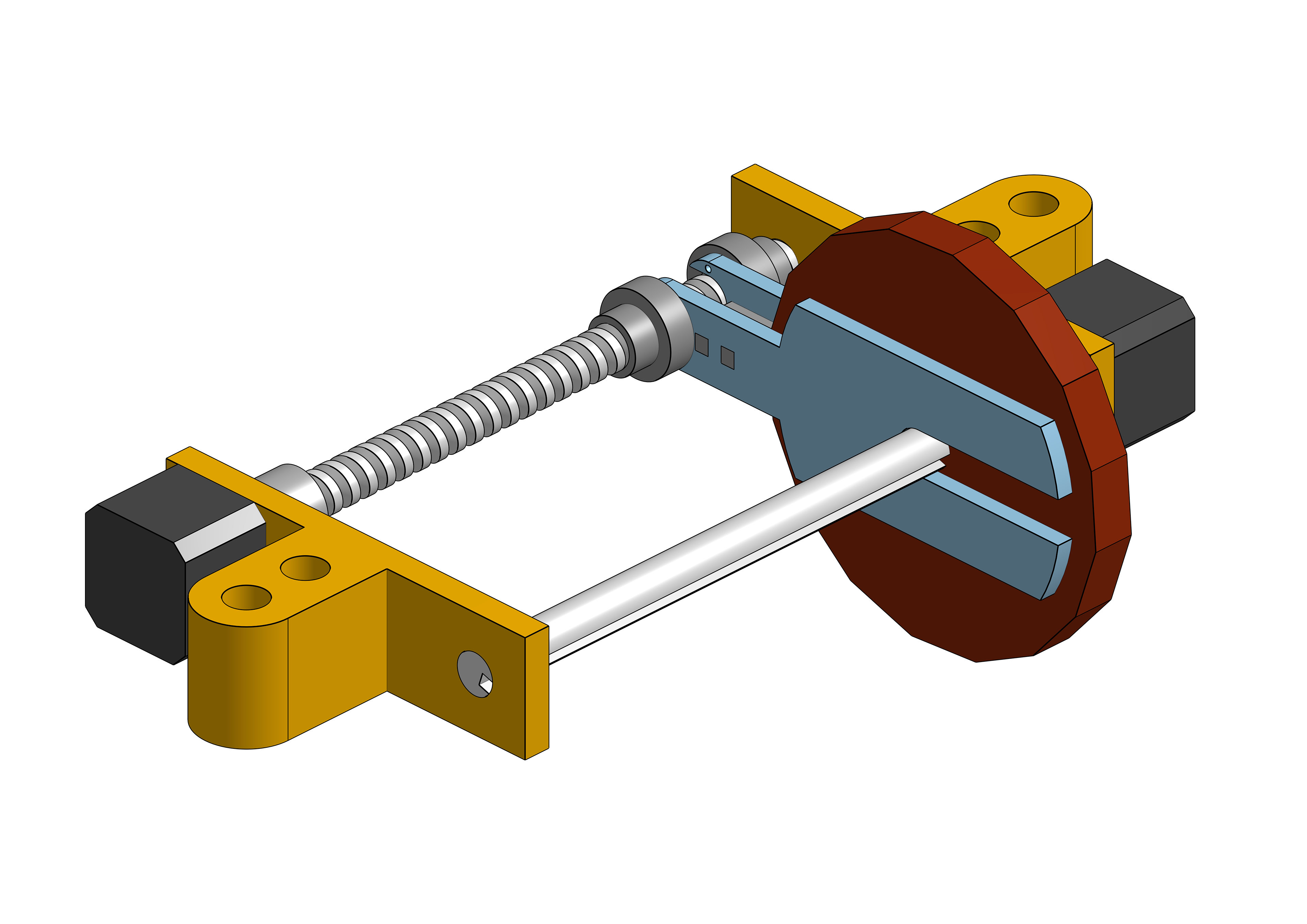
Beginning of Prototype A chaddis design.
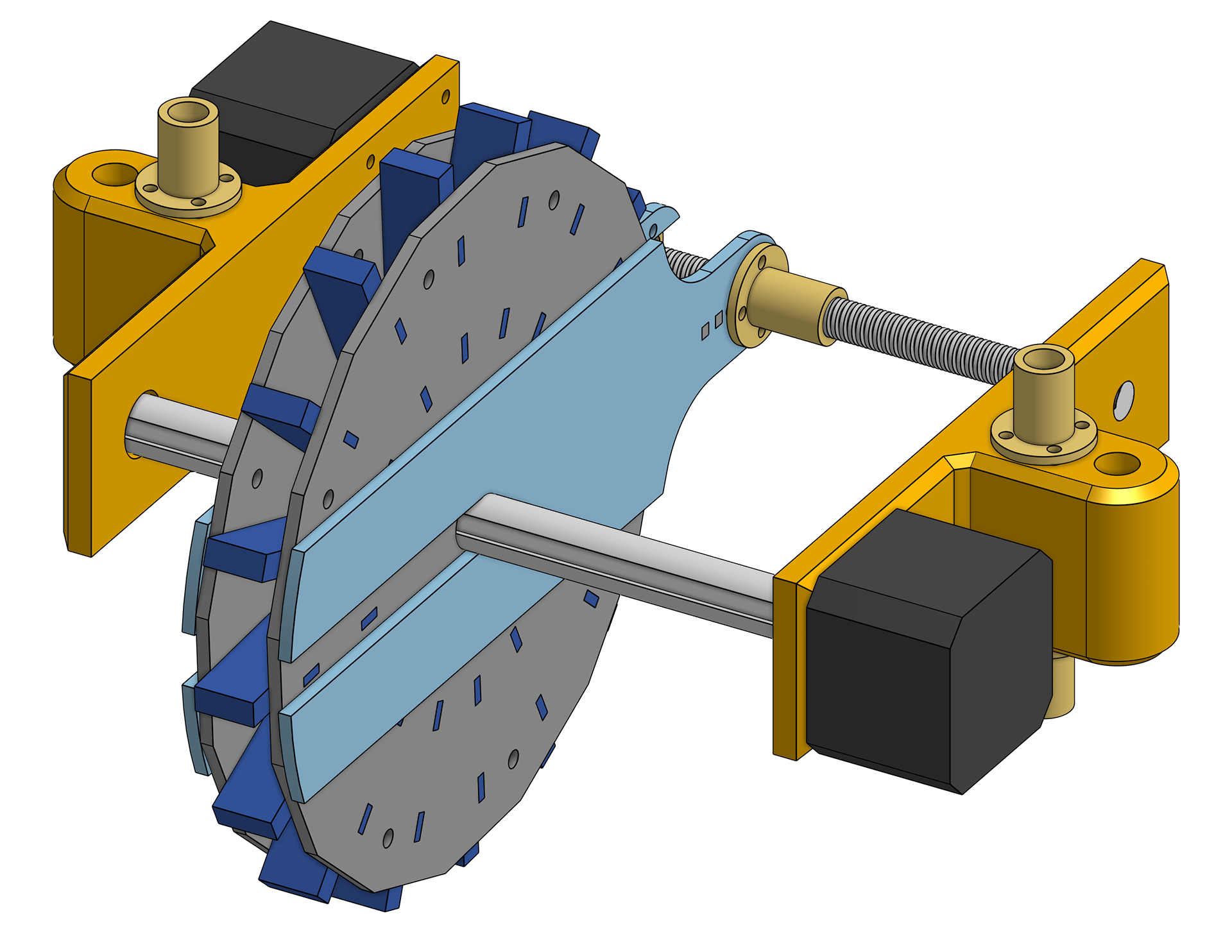
End of Prototype A chassis design.
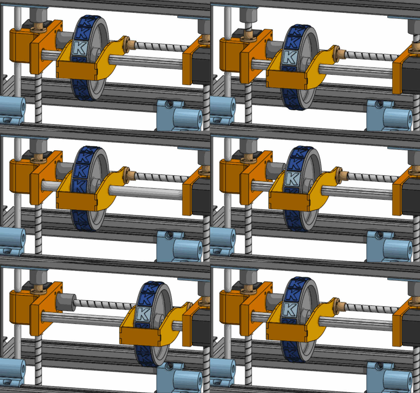
Prototype B chassis design.
Wheel Tests
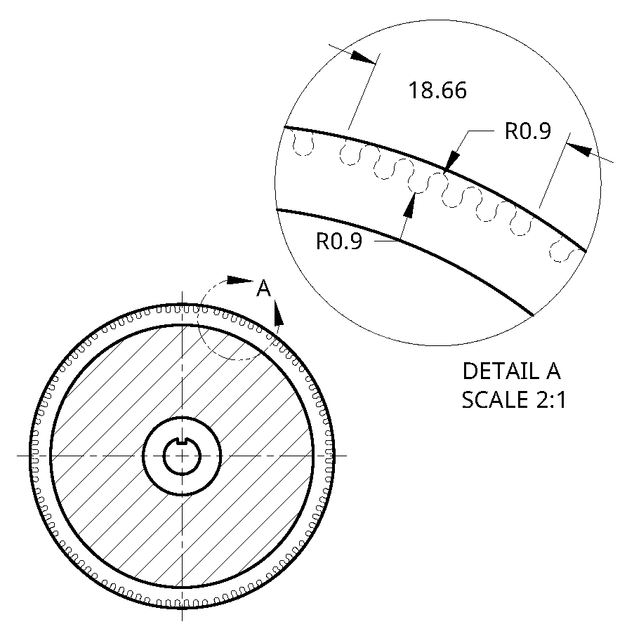
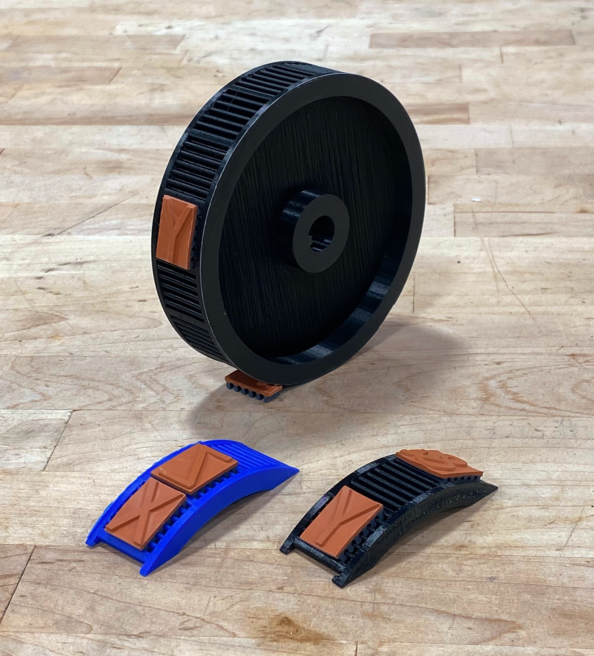
I performed tests to determine how our new stamper wheel would be designed. Since the stamps were not as tall, the profiles could be placed side-by-side and the overall radius decreased. Since they were made of rubber and I wanted the stamps to be removable, I used the small nubs in the backs of the stamps to create a press-fit into the geometry of the wheel. Two trials were conducted between the use of a Prusa Mark4 using PLA and a Stratasys F120 using ABS-M30, and the Mark4 fit our needs slightly better.
The Binding Problem
One major problem in both prototypes was that the stamper wheel would catch on the keyed shaft when attempting to move horizontally. We discovered this was due to unbalanced forces exerted on the wheel from the acrylic plates making up the slider. When the slider lead screw was turned, the acrylic plates would skew outwards slightly, and apply normal forces exclusively on the outer edges of the stamper wheel. This would create a torque around its center, and it would catch on the keyed shaft. To solve this, we first tried acrylic spacers that would attempt to stabilize the slider plates, and while this helped alleviate some problems, the binding would inconsistently return. Our final solution was introducing two linear bushings directly next to the keyed shaft, minimizing normal forces that introduced torque on the system.
The Sequencing Problem
Our motors operated on a general principle called sequencing, in which each coil within the stepper motor would be set to HIGHT or LOW in a specific order to turn the rotor in a direction. We initially programmed our motors to use a whole-step sequence, which contains four “stages”, each corresponding to one “step” which would repeat for as long as you wanted the motor to run. For our Nema steppers, 200 of these steps would comprise one full rotation. Since we were using hexadecimal, it needed to turn 1/16th of a rotation (or 12.5 steps) for each character. We decided to use half-steps, which uses two “stages” per step and eight stages total. Each motor object would now also keep track of where it was inside a sequence so that it would not skip any stages, resulting in an overall increased accuracy.
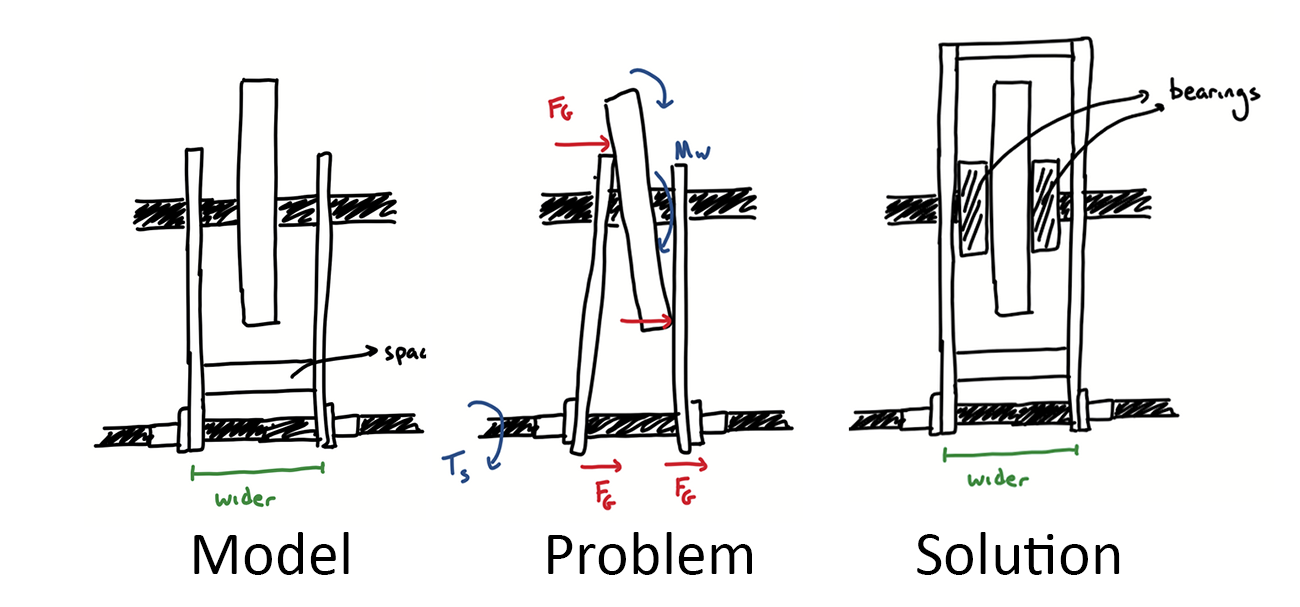
The initial design, the primary forces problem, and the final bushing solution.
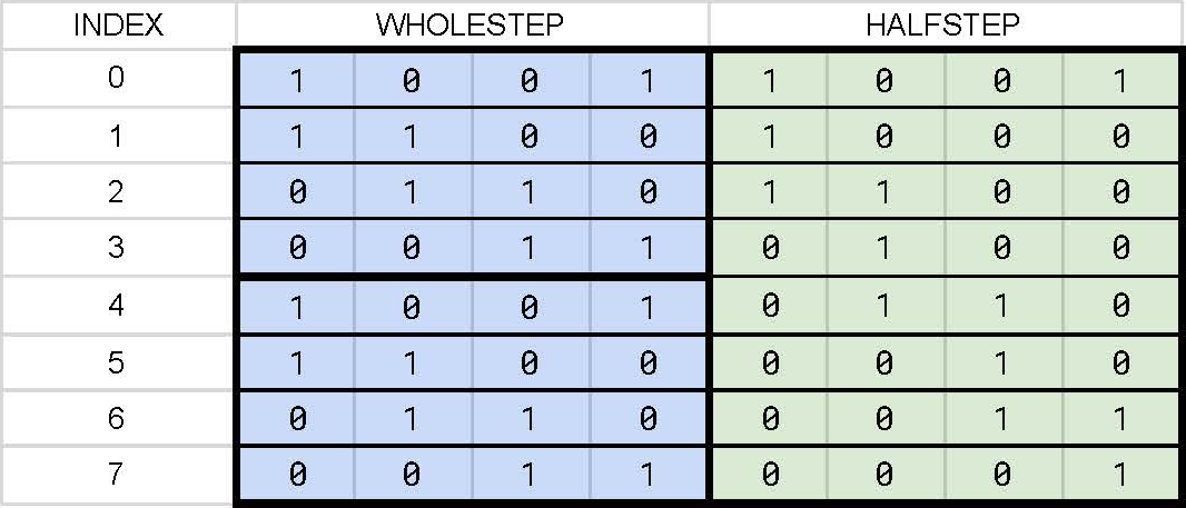
Each colored column represents a specific motor lead, a 1 means it is set HIGH, and a 0 means it is set LOW.
Sweeper
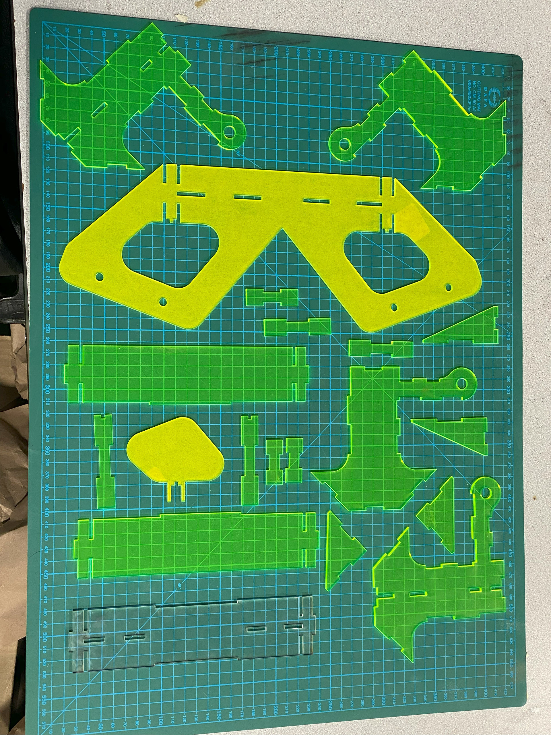
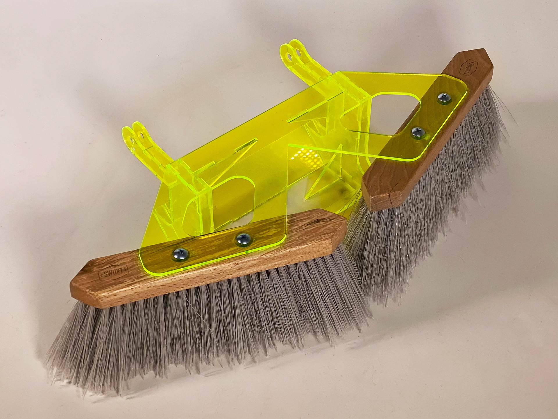
Since we needed to have a part of our design that tackled cleaning the floor in front of the stamper to combat dust accumulation, we talked to the Amazon representatives about how this could manifest in our design. With given freedom, we came up with a few design ideas of a "sweeper", that could clean the floor with dry dusting pads.
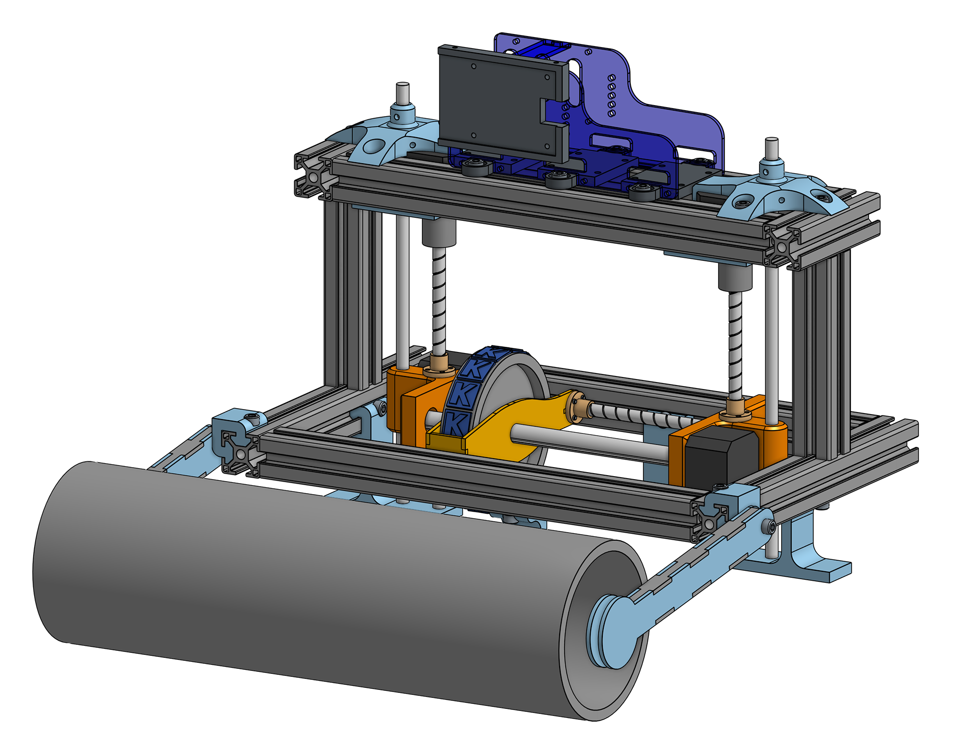
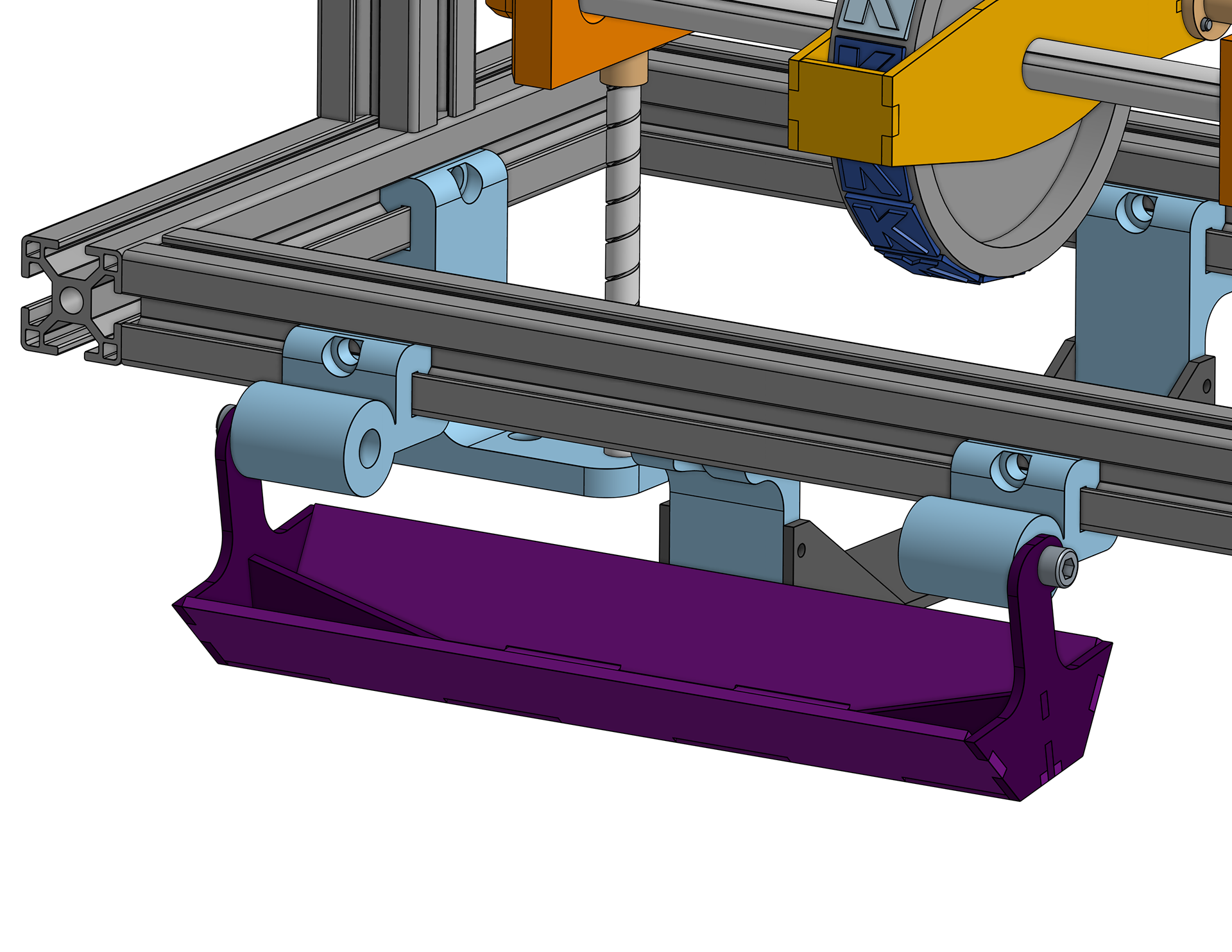
I modeled a few iterations, and then the final design that we would end up using in our final prototype. It incorporated two angled broom heads for large particulates, as well as a dry sweeping pad behind them to pick up finer debris. This was primarily made from laser-cut cast acrylic and purchased broom heads.
Final Design
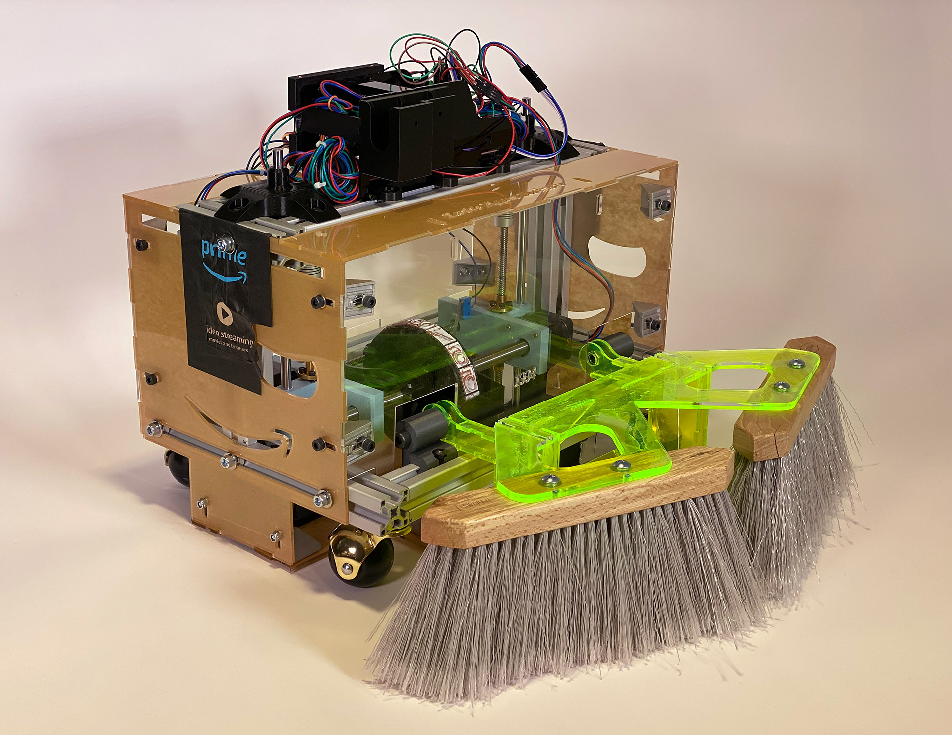
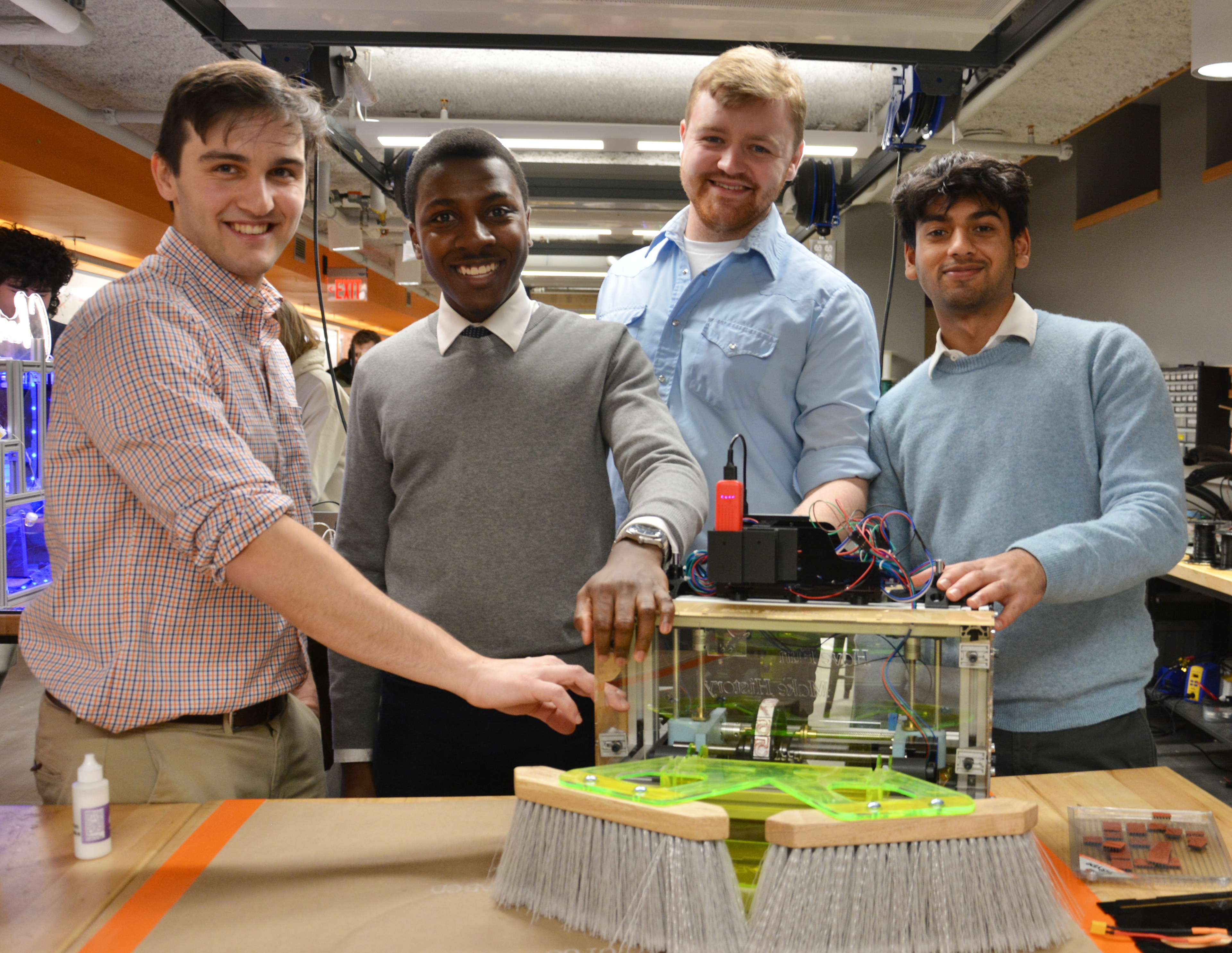
Our last tasks were to create a dust-proof casing for the overall frame and an electronics housing to hold the Raspberry Pi and other electronics. These were additionally created with acrylic and affixed to the frame with various hardware. We then tested our robot, creating many successful code printings on paper during our showcase.
Additional Media
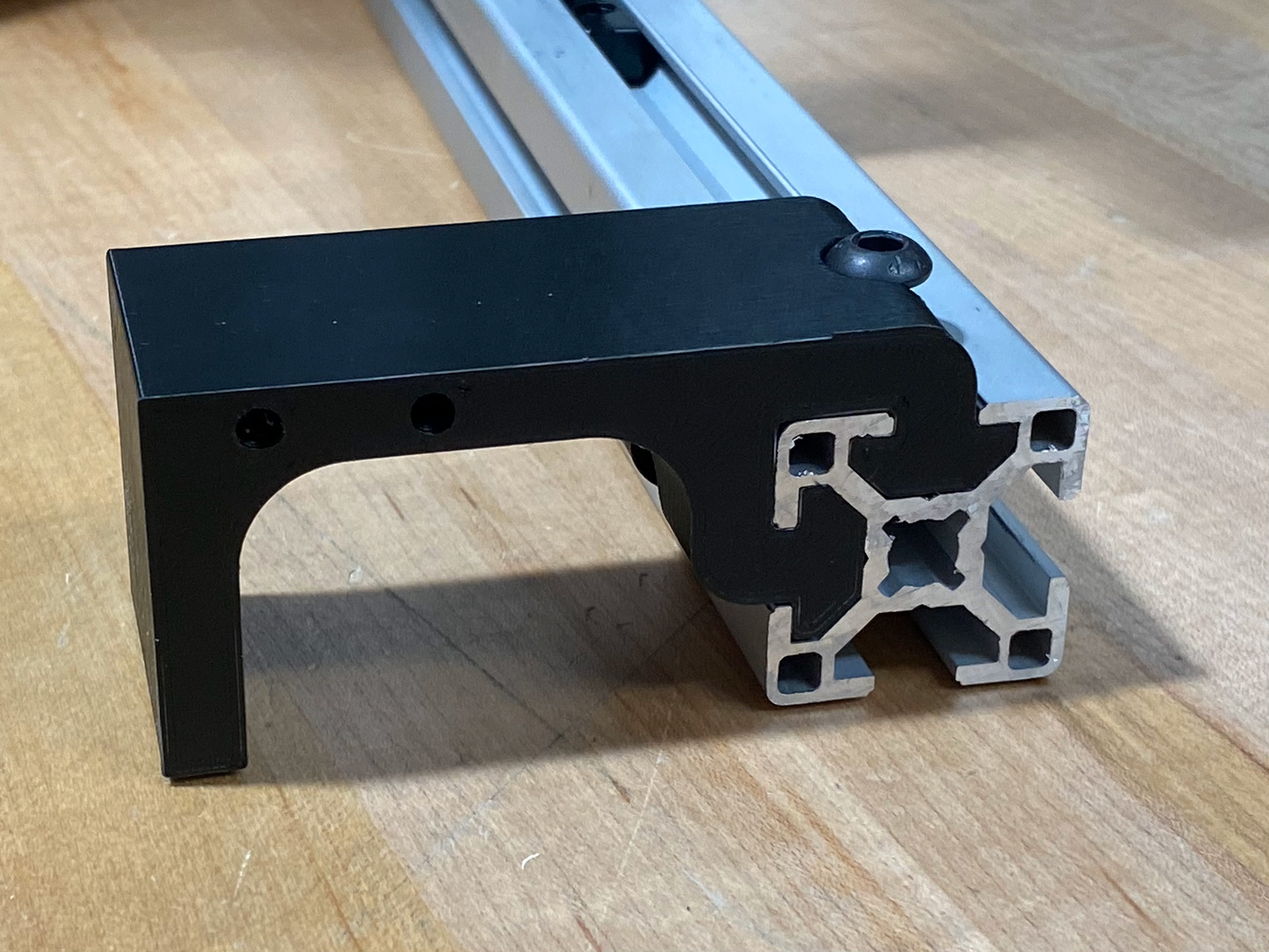
A custom brace I modeled for support of the vertical lead screws.

A snapshot of the Python code used for the stamper.
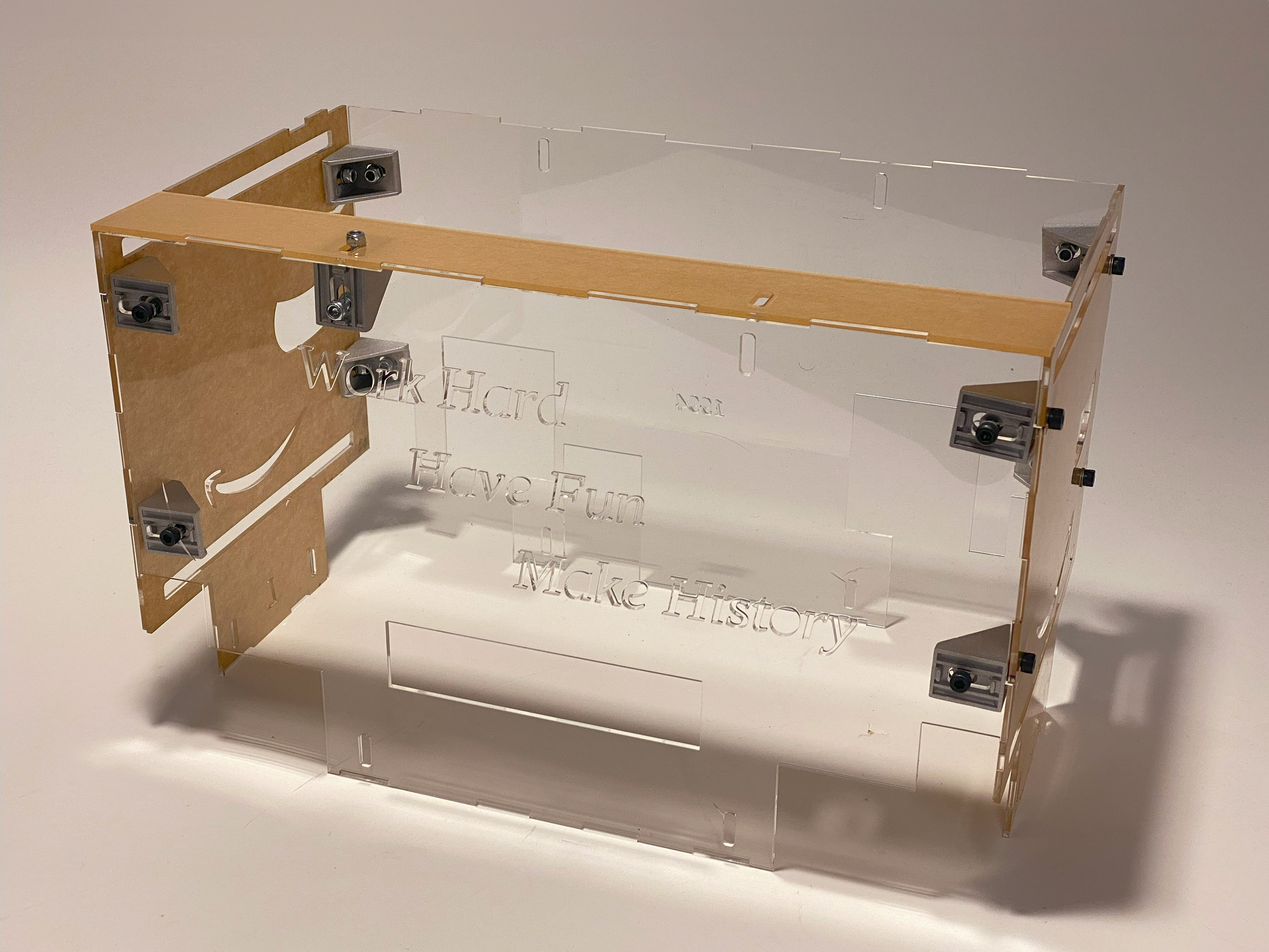
The casing used to protect against debris designed by Marc Alenn Jean Mary.
A small recording of stepper motor sequence testing.
CAD of the finalized full model.

