The goal of this project was to fully model an H-Bridge circuit that would use 12V power and input pins and allow for a motor to be used in multiple directions via alternating directions of current.


Initial Circuit Construction
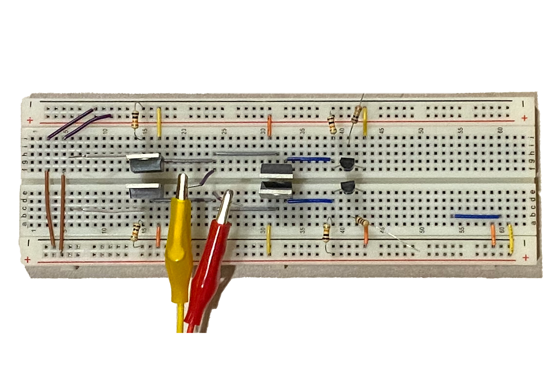
The first step in creating a printed circuit board is to design the circuit. For an H-Bridge, there must be a driving voltage inlet, as well as two control pin terminals to manage the state of the primary gate, and a terminal for a motor. This was first designed on a breadboard and then modeled within KiCad. Tests were run to confirm functionality and continuity.
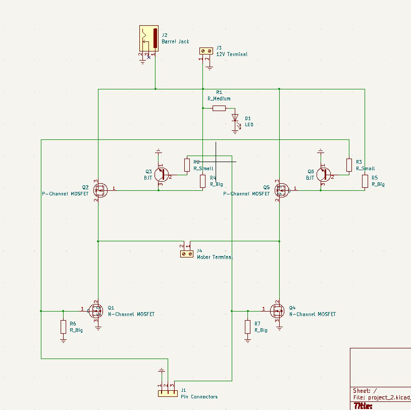
Physical Board Layout
Once the model for the circuit was made, each component needed to be assigned a "footprint" that corresponded to a real-life electronic component. This was done for each of the MOSFET, BJT, terminals, LED, and resistors included in the design. Once completed, the layout for where each of these components would live and how they would be connected on the physical board had to be decided. While not completely optimized for space, the design created allowed for easy access to each of the terminals.
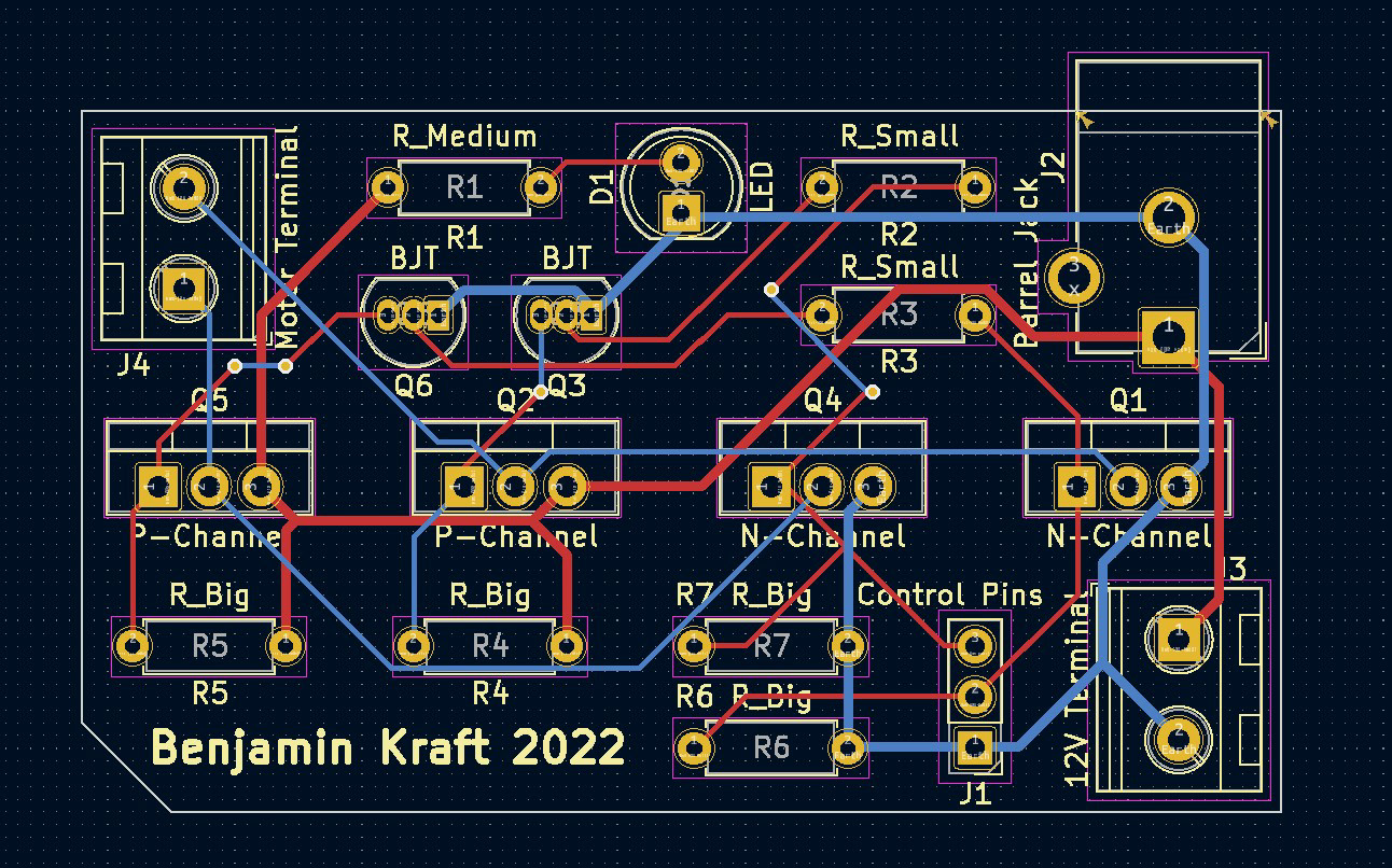
Copper lead connector layout. Red indicates top of the board, blue indicates bottom.
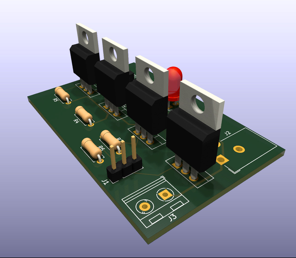
A final render showing how the components would fit on the completed board.
Printing
Once complete, the models were sent to an online manufacturer. The board would be "printed", layer by layer with the specified dimensions and labeling. When delivered, each of the components was soldered to the board and it could now be used as a functional H-Bridge.

