

Why am I Throwing a Robot Against a Wall?
I joined the Robot Locomotion & Biomechanics Laboratory at Tufts University under Dr. Matthew Woodward in 2021 and gravitated towards working on a "Gripper" robot. As a part of a larger jumping-gliding-gripping robot, the goal of this project is to create a passive device to "hang" onto a vertical surface and not expend excessive energy. This could be an angled or rounded corner, or eventually a flat surface. Our existing design uses a spring to close two feet around a corner and attempt to grip. With a basic swinging rig to throw the design, the robot was not able to grip any surface. A large part of this project that I wanted to complete was to fabricate a more consistent testing rig allowing us to achieve more precise velocities and throw angles.
Creating a Precise Throw
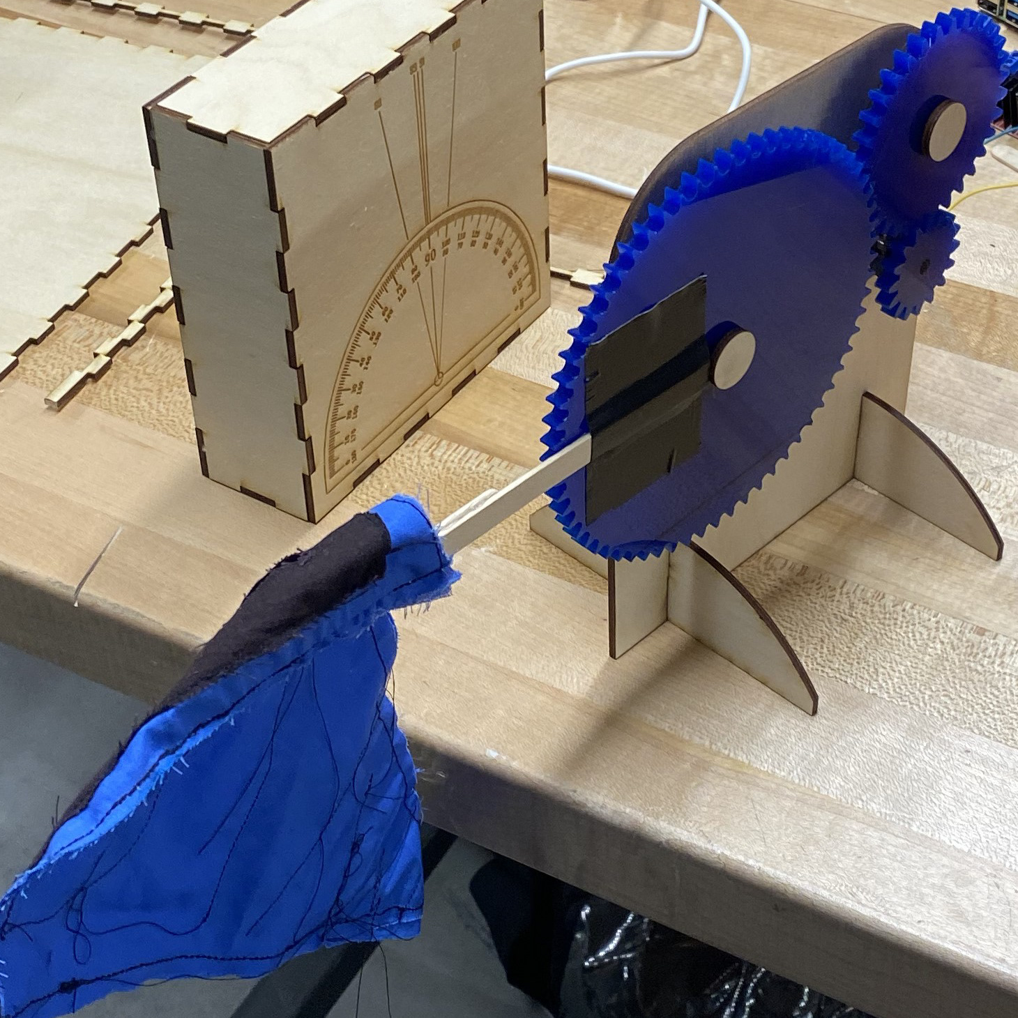
A secondary goal was to create a system to "throw" the robot itself. This included many drafted designs but ended up using a specific "release" angle so that at the throw point, the robot would be launched with a specific velocity and angle relative to horizontal. This was achieved by a separate "stopper" that the swinging arm would impact, as well as two acrylic plates; One would hold the stopper at a specified throw angle, and the other with calculated release points from which the arm could be set.
Designing a Testing Rig
One of my first goals for the overall project was to create a precise and deterministic testing rig from which to throw the gripping robot. Work was done in 3D modeling and printing to iterate on a previous design and come up with methods for a "release" and "throw" phase.
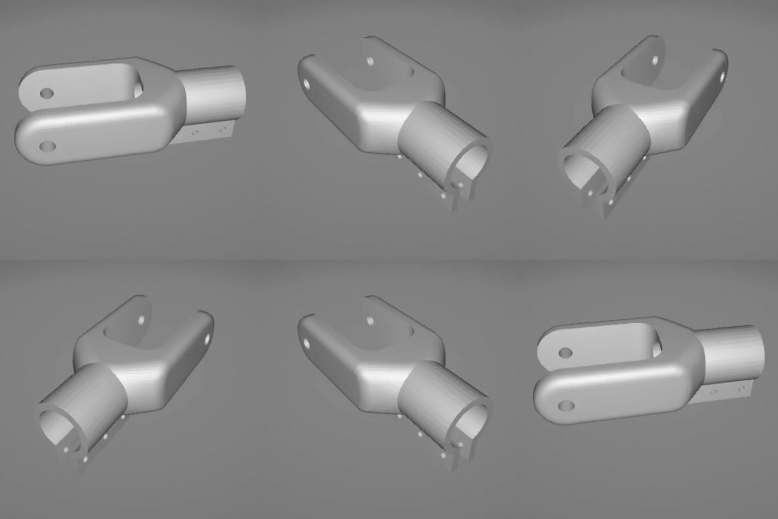
A "hinge-to-bar" mount model
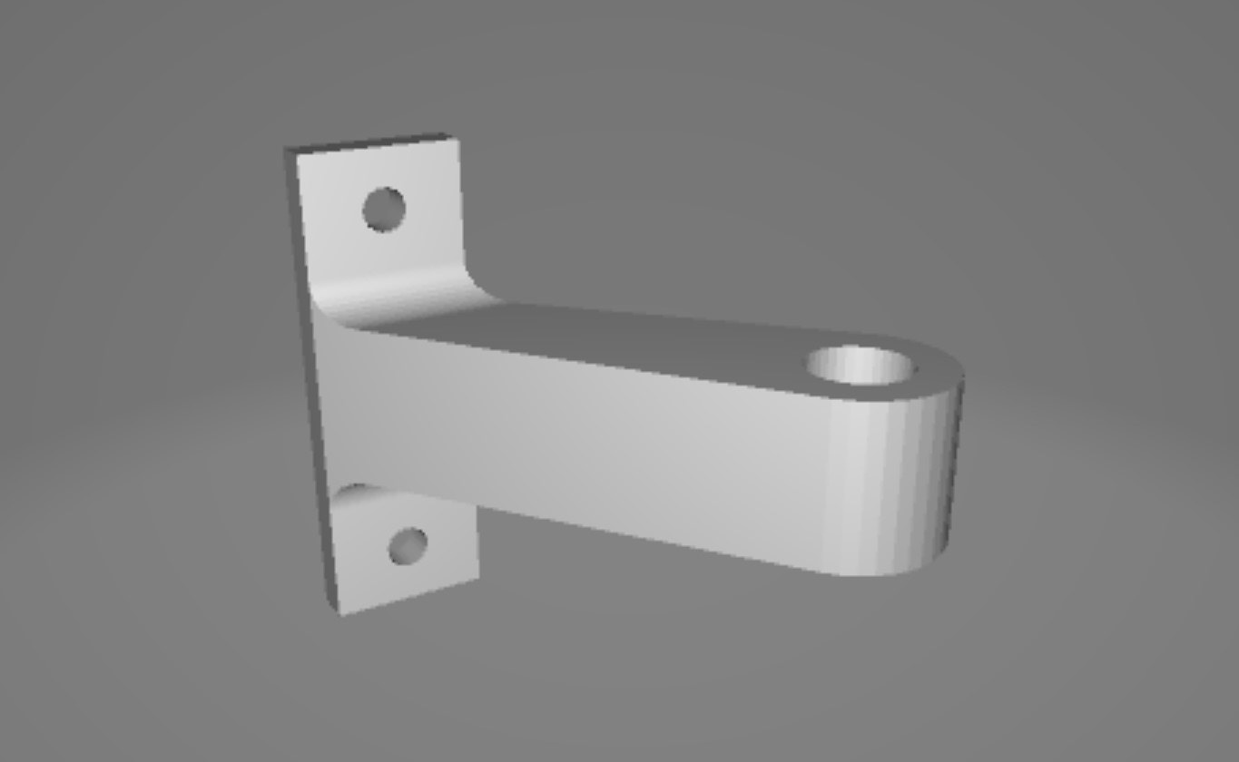
A "hinge-to-extrusion" mount model

A 3D mockup of the overall testing setup
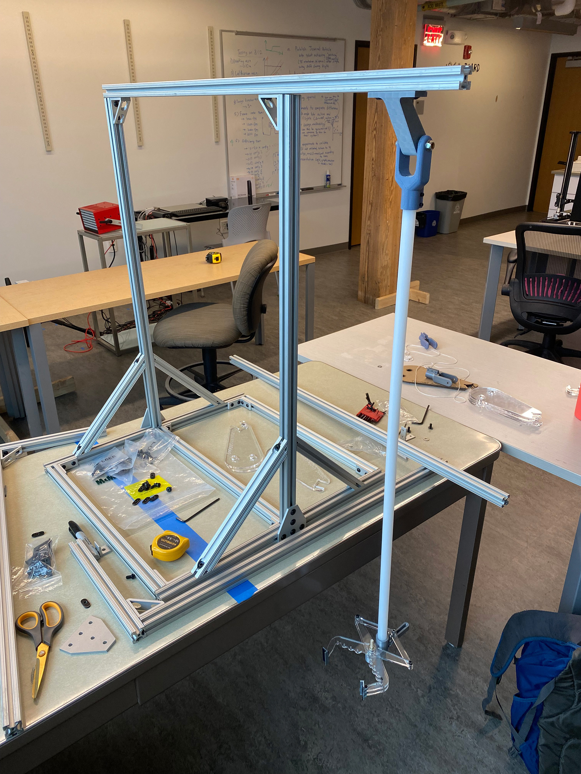
An assembled testing rig with arm in place

Sketches of a proposed stopping mechanism

Sketch of another proposed stopping mechanism
Releasing in Time
To avoid a hard stop when the swinging arm reached the stopper, I used a limit switch and linear solenoid in series to throw the robot slightly before the correct angle was met. A mount was made for the swinging pole, and once the limit switch was activated, the solenoid would open the gripper. A simple circuit connected the solenoid directly in series with the limit switch and a power supply to minimize the delay.
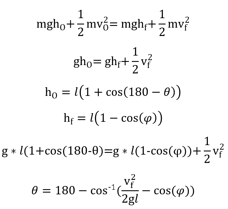
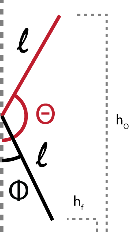
A diagram for calculating "release" angles


A drawing of the solenoid and limit switch components

A sketch of the assembled setup with the gripper
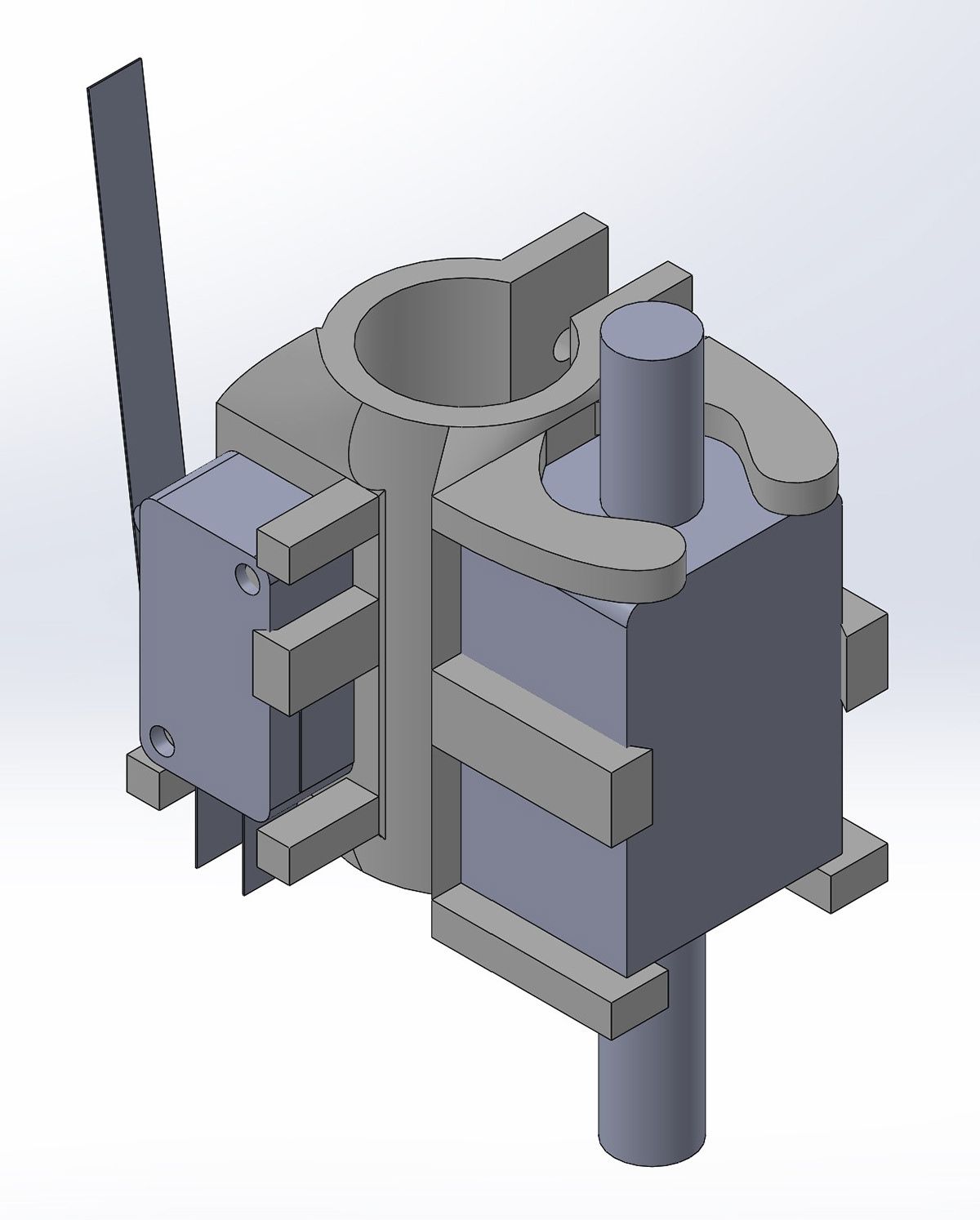
A model mockup for a pole mount
New Pin Designs
Once the testing rig was completed, work began on new "foot" designs to allow the gripper to hold onto various surfaces. My first design was as simple as possible, in which two opposing pins were used to apply opposite compressive forces on a surface. These pins' angles could be adjusted, to try and find the optimal collision angle for each surface type. The 6mm carbon fiber tubes were kept from the existing design to offset the pins from the hinge mechanism.
Future Work
The majority of future work involves testing the pin model at various velocities and angles. The primary statistic that will be recorded is if the gripper can attach to the given vertical post surface or if it fails to do so completely. There will be three primary independent variables: The angle of the throw, the velocity of the throw, and the angle of the gripper pin. There was a successful preliminary throw at 0 degrees from horizontal to a vertical wooden surface at 2 m/s.

